Introduction
Transcatheter aortic valve replacement (TAVR) has revolutionised treatment of severe aortic stenosis (AS) and expanded indications from inoperable and high-risk patients to intermediate-, and potentially soon, to low-risk patients1,2,3,4,5. Improving TAVR outcomes by reducing paravalvular leakage (PVL) has required optimal transcatheter heart valve (THV) sizing, which is primarily based on ECG-gated computed tomography angiography (CTA)6,7,8,9. Selection of the appropriate THV size to implant is based on aortic annulus sizing, which is dynamic, dependent on timing of the cardiac cycle. Timing of CTA image acquisition during diastole vs systole impacts annulus size measurements, and systolic gating to measure maximum annulus area is primarily used for THV size selection8. Some patients’ annulus sizing falls within areas of “grey zones” between two THV sizes, both of which can be considered appropriate. Clinical decision-making is often guided by parameters such left ventricular outflow tract (LVOT) calcification and risk of annular rupture10, anticipation of degree of PVL6,7,9, sinus effacement, and sinotubular junction dimensions.
However, the degree of THV under- or over-sizing impacts the deployed THV shape and leaflet coaptation11,12. Such changes in THV configuration can affect leaflet stresses. Prior THV biomechanical studies have suggested that greater leaflet stresses accelerate THV degeneration and limit long term durability13,14,15,16,17. There is no method to directly measure leaflet stresses, thus computational methods such as finite element analysis (FEA) are valuable for providing such data, which assess failure modes. Accurate finite element (FE) models require precise 3D geometry in a zero-stress state, material properties, and physiologic loading conditions. Our previous FEA studies have determined THV leaflet stresses on specific sizes of first-16, second-17, and third-generation15 SAPIEN, SAPIEN XT, and SAPIEN 3 valves (Edwards Lifsciences Inc., Irvine, CA, USA) under quasi-static loading conditions based on micro-CT images. However, the impact of THV size on THV leaflet stresses is unknown. For each generation of Edwards balloon-expandable THV, there has existed “grey zones” where either of 2 sizes of THV are suitable. Thus, it is helpful to examine leaflet stresses of different sizes of THV and also to understand the impact of under- or oversizing THV within the annular “grey zones.”
Edwards SAPIEN XT, a second-generation bovine pericardial balloon-expandable valve, was designed with a cobalt-chromium stent with fewer rows and columns between the commissures compared to the first-generation SAPIEN, allowing reduction in THV profile for smaller delivery systems18. In the SAPIEN XT sizing chart, 23 mm XT was optimal for annulus diameters of 19-22 mm, and areas of 300-380 mm2, while 26 mm XT was optimal for diameters of 23-25 mm, and areas of 415-490 mm2. As such, a grey zone existed between diameters of 22-23 mm, and areas of 380-415 mm2 in which either size 23 mm or 26 mm XT could be chosen for a given patient. Similarly, 29 mm XT was optimal for annulus diameters of 26-28 mm, and areas of 530-620 mm219. Thus, between diameters of 25-26 mm, and areas of 490-530 mm2, either 26 mm or 29 mm XT could be chosen for a patient. Choosing the smaller THV would result in THV oversizing (overexpansion of a smaller sized THV), while choosing the larger THV would result in THV undersizing (underexpansion of a larger sized THV). Based upon the availability of three sizes of commercial SAPIEN XT, our goal in this study was to determine THV leaflet stresses with increasing THV size to understand the impact of choosing a given THV size on future long-term durability using XT THVs as an example.
Materials and methods
Commercial 23 mm, 26 mm, and 29 mm Edwards SAPIEN XTs were obtained. A fully expanded THV assembly consisted of 3 components: cobalt-chromium stent, Dacron skirt, and bovine pericardial leaflets. Suture connections between different components were included to enable accurate simulation of the assembly with its connections. The process to determine THV stress distribution included: 1) microCT scanning of each individual THV, 2) 3D reconstruction of THV components, 3) FE simulation to mimic in vivo blood pressure and deployment, and 4) post-processing and data analysis to determine stresses on leaflets and stents.
TRANSCATHETER AORTIC VALVE RECONSTRUCTION
SAPIEN XT valves were imaged with a desktop cone-beam micro-computed tomography scanner (microCT-40; Scanco Medical AG, Baseldorf, Switzerland) in different orientations and intensities to distinguish stent and leaflet geometries as previously described15,16,17. High-resolution DICOM (Digital Imaging and Communications in Medicine) radiologic images were imported into MeVisLab image processing software (MeVis Medical Solutions AG, Bremen, Germany). Images were manually segmented to separate THV stent vs. leaflets and obtain the most accurate representation of each of the three TAVR sizes. Reconstructed geometries were then imported into Geomagic Design X® (3D Systems, Rock Hill, SC, USA) to create the geometric model, which was used to generate volumetric mesh in TrueGrid® (XYZ Scientific Applications, Inc., Pleasant Hills, CA, USA). Convergence studies were performed to determine optimal mesh density. The mesh was refined until the stress results varied <5% for two subsequent mesh refinements20. Ultimately, 20,988 elements were chosen for the leaflets on the 23 mm, 26 mm, and 29 mm SAPIEN XT valves, 6,336 elements for the stent, and 1,848 elements for the Dacron skirt. Leaflets, stent, and Dacron were precisely reconstructed and aligned to create the entire THV model. Leaflets were attached to the Dacron and stent along suture lines. The geometry and mesh of a representative THV are shown (Figure 1 and Figure 2). Stent geometry was modelled using 3-dimensional brick elements, while leaflet geometry was modelled using nonlinear shell elements.
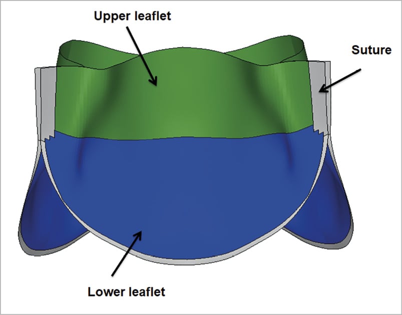
Figure 1.Transcatheter heart valve leaflet assembly. Regions of interest studied for stress distribution in leaflets: upper leaflet free edges; lower leaflet belly; and sutured leaflet edges.
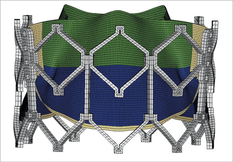
Figure 2. Transcatheter heart valve mesh. Representative mesh of 23 mm SAPIENXT with leaflet assembly and stent frame.
FINITE ELEMENT ANALYSES
Deployment and dynamic systemic pressure loading were performed using ABAQUS (Dassault Systems, Waltham, MA, USA). Contact definitions between the pairs of inner leaflets, leaflet and stent, leaflet and Dacron, and stent and Dacron were defined to most accurately represent the contact interaction behaviour. THV leaflet geometries were sutured to the stent at the commissure area and sutured to the Dacron mesh along the bottom edge as seen in Figure 2. Leaflets of the SAPIEN XT valve are composed of bovine pericardium which is specially treated to resist calcification, a proprietary process that is also used for corresponding surgical Carpentier-Edwards Magna pericardial valves (Edwards Lifesciences, Inc.). Biaxial stretch testing of these surgical valve leaflets (n=12 with 35 valve leaflets) was performed to determine the material properties of THV leaflets21 and the constitutive material model was previously described16,17. A nonlinear regression Levenberg-Marquardt least squares algorithm in MATLAB (version 2014a, MathWorks, Natick, MA, USA) was used to fit experimentally obtained stresses to find the best-fitting material constants.
Pressure loading was applied to the fully expanded THV at nominal geometry or to the deployed geometry. Superior surfaces of leaflets and all the surfaces of the stent were subjected to dynamic loading of systemic pressures. After the initial pressurisation, cardiac cycles of 800 ms duration were applied. Each cardiac cycle was composed of a 300 ms ramp upwards to maximum systolic pressure, followed by a 500 ms ramp downwards to minimum diastolic pressure.
A repeatability study to verify the stress results was performed and the repeatability was satisfactory. One of the study authors (Z. Wang) independently re-created the models of all three sizes of SAPIEN XT valve from the micro-CT images, and ran pressure loading simulations. Stress distribution on the leaflet and stent of each size was nearly identical to the original model, and variation of the peak stress magnitudes was 6.28%±3.84% (mean±SD), which was within the range of the previous interobserver study22.
Results
For SAPIEN XT leaflets, the maximum principal stresses across the entire leaflet, including sutured regions, were 1.69 MPa, 1.70 MPa, and 2.12 MPa for 23 mm, 26 mm, and 29 mm XT, respectively, at mean arterial pressure of 93.3 mmHg (Figure 3A-Figure 3C). Minimum principal stresses across the entire leaflet, including sutured regions were –0.37 MPa, –0.29 MPa and –0.24 MPa for 23 mm, 26 mm, and 29 mm XT, respectively, at mean arterial pressure (Figure 3D-Figure 3F). Maximum and minimum principal stresses for each region in 23 mm, 26 mm, and 29 mm XT are listed in Table 1. Positive stress values correspond to tensile stress where THV leaflets are stretched to provide coaptation, while negative stress values represent leaflet compression or bending where redundant tissue was compressed in order to coapt. Peak stresses occurred at tips of leaflet commissures along the attachment with the stent in the 23mm and 29 mm XT and occurred at the bottom suture of leaflet to the Dacron in 26 mm XT (Figure 3). In contrast, regions of free leaflet margin at the top and leaflet belly at the bottom had lower peak stresses for all three sizes.

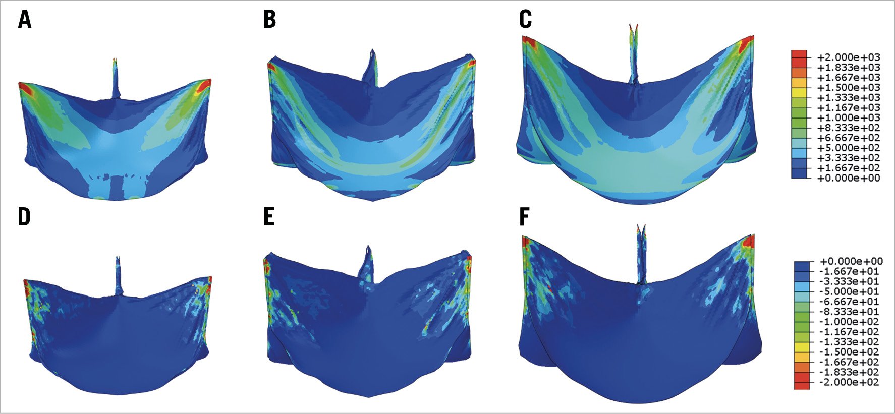
Figure 3. Maximum and minimum principal stresses on transcatheter heart valve leaflets. Maximum (A-C) and minimum (D-F) principal stresses on entire leaflet of 23 mm, 26 mm, and 29 mm SAPIEN XT at mean arterial pressure.
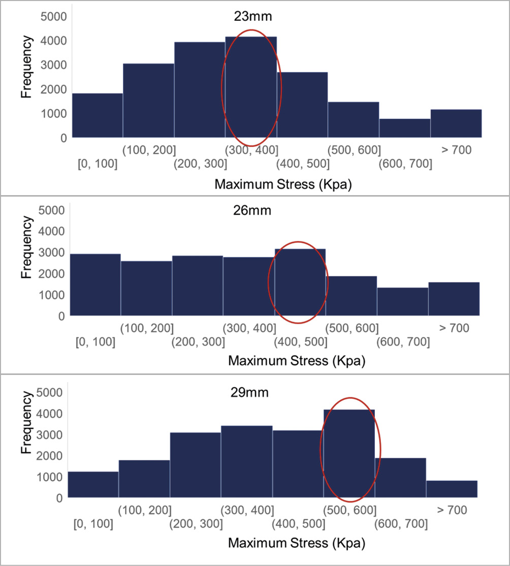
Figure 4. Histogram of leaflet stress values. Histogram of leaflet stress distribution for three SAPIEN XT sizes. Circled bar indicates range with highest frequency.
Stress distribution on leaflets of each THV size was analysed and plotted on histograms (Figure 4). Surface areas of each leaflet were 304 mm2, 338 mm2, and 392 mm2 for 23 mm, 26 mm, and 29 mm XT, respectively. Median values of maximum principal stresses were 0.32 MPa, 0.35 MPa, and 0.41 MPa with increasing THV size, 23 mm, 26 mm, and 29 mm XT, respectively. Examining the most frequent leaflet stress values by histogram, they fell within the range of (300, 400), (400, 500) and (500, 600) kPa for the 23 mm, 26 mm, and 29 mm XT, respectively (Figure 4).
To determine THV leaflet stresses for annulus sizes within the grey zones, we deployed 23 mm and 26 mm XT valves within an annulus of area 398 mm2, which clinically would require balloon oversizing the 23 mm XT and undersizing the 26 mm XT. When deployed within the same size annulus, leaflet stresses were compared. Stress distribution in the undersized 26 mm XT was greatly shifted towards lower stress levels (Figure 5), while stress distribution in the oversized 23 mm XT did not change significantly from its fully expanded position and overall, had higher frequencies of high stress concentrations than the 26 mm XT valve. Similarly, we deployed the 26 mm and 29 mm XT valves within grey zone of annulus area 511 mm2. Leaflet stresses on the undersized 29 mm XT again were greatly shifted towards lower stress levels (Figure 6), while the oversized 26 mm XT showed minimal change in stresses from its nominal geometry, but overall had higher frequencies of larger stress concentrations than the undersized 29 mm XT valve.
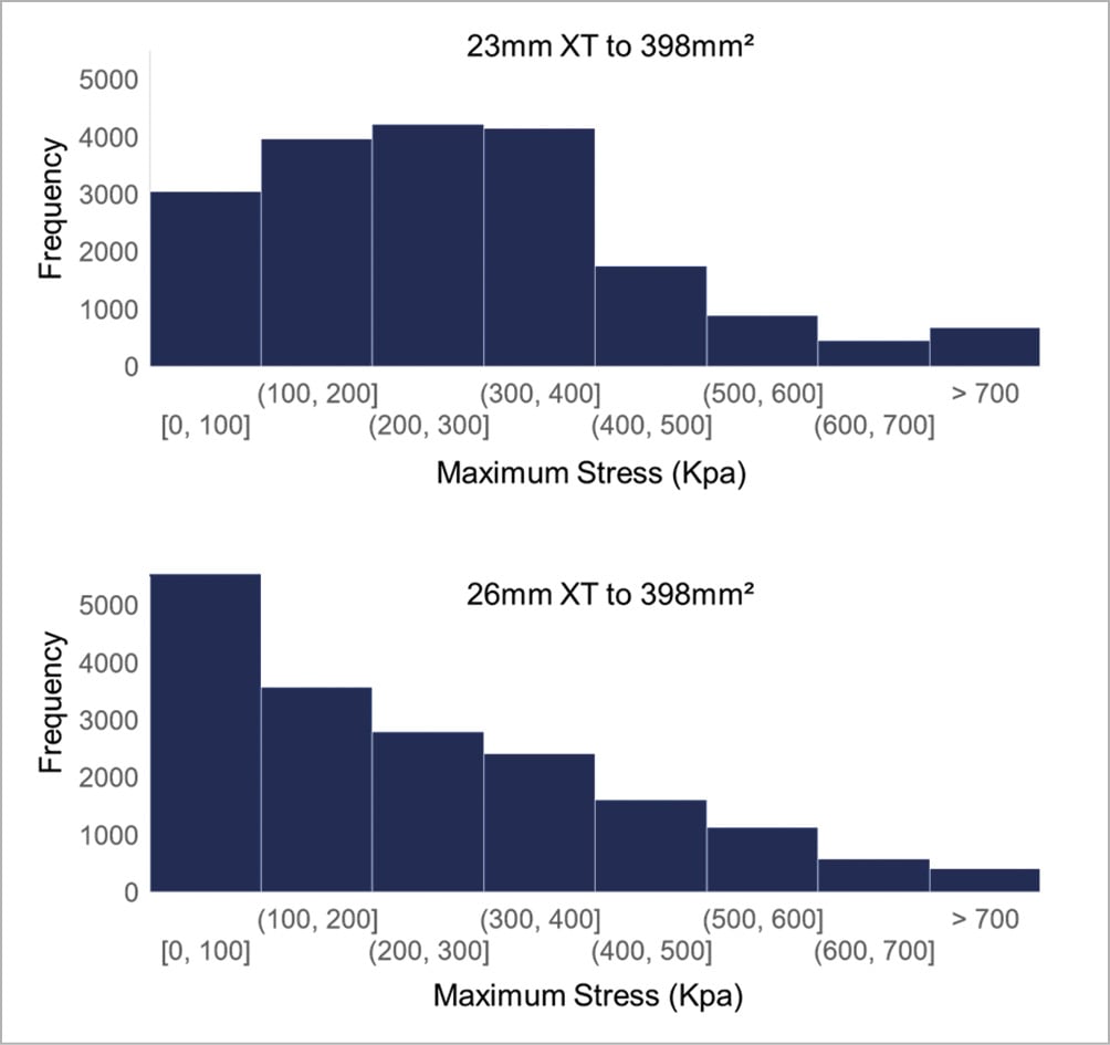
Figure 5. Leaflet stress histogram for 23 mm and 26 mm SAPIEN XT deployed to 398 mm2. Histogram of stress distribution on leaflets of 23 mm and 26 mm SAPIEN XT deployed to 398 mm2. The y-axis value represents the number of elements in the model experiencing the specified range of stress defined by the x-axis bin-width.
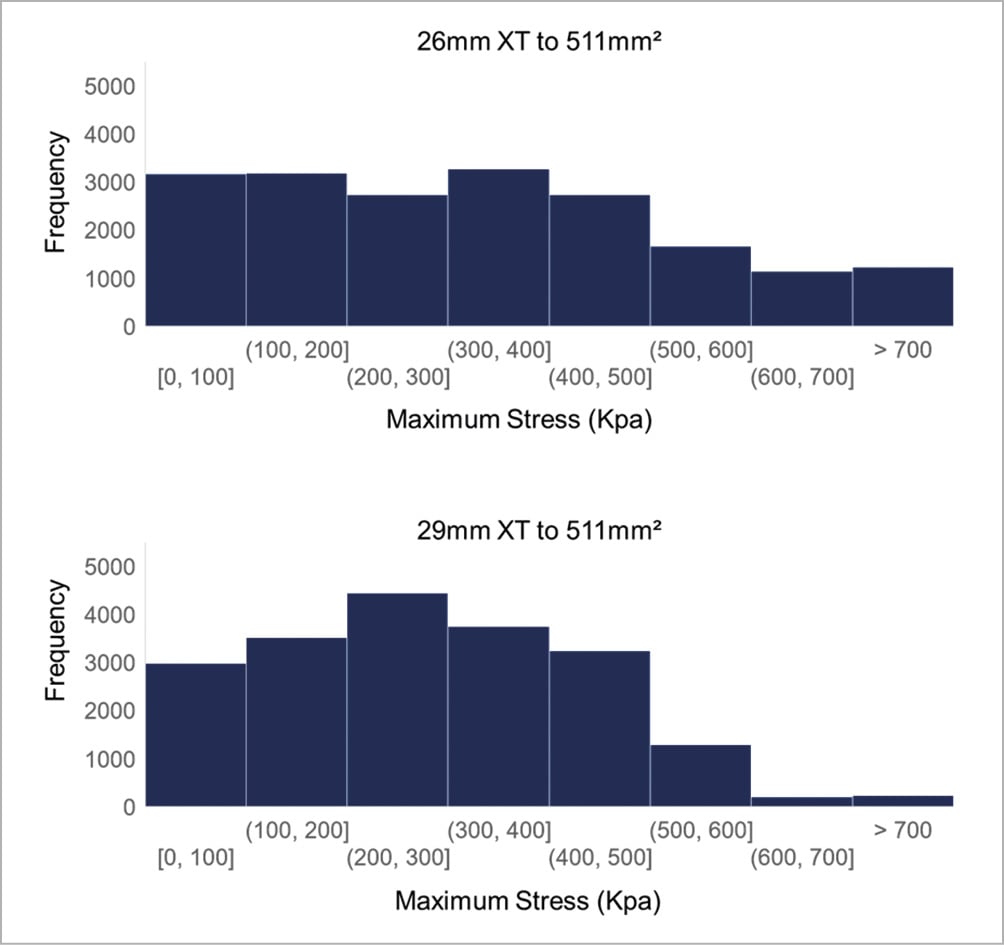
Figure 6. Leaflet stress histogram for 26 mm and 29 mm SAPIEN XT deployed to 511 mm2. Histogram of stress distribution on leaflets of 26 mm and 29 mm SAPIEN XT deployed to 511 mm2. The y-axis value represents the number of elements in the model experiencing the specified range of stress defined by the x-axis bin-width.
For the SAPIEN XT stent, maximum principal stresses at mean arterial pressure were 54.91 MPa, 47.33 MPa, and 53.11 MPa, for 23 mm, 26 mm, and 29 mm XT, respectively; minimum principal stresses at mean arterial pressure were –52.12 MPa, –48.78 MPa, and –50.17 MPa, for 23 mm, 26 mm, and 29 mm XT, respectively (Figure 7). Peak stresses occurred on the stent in proximity to the simulated patient annulus and at distal frame elements.
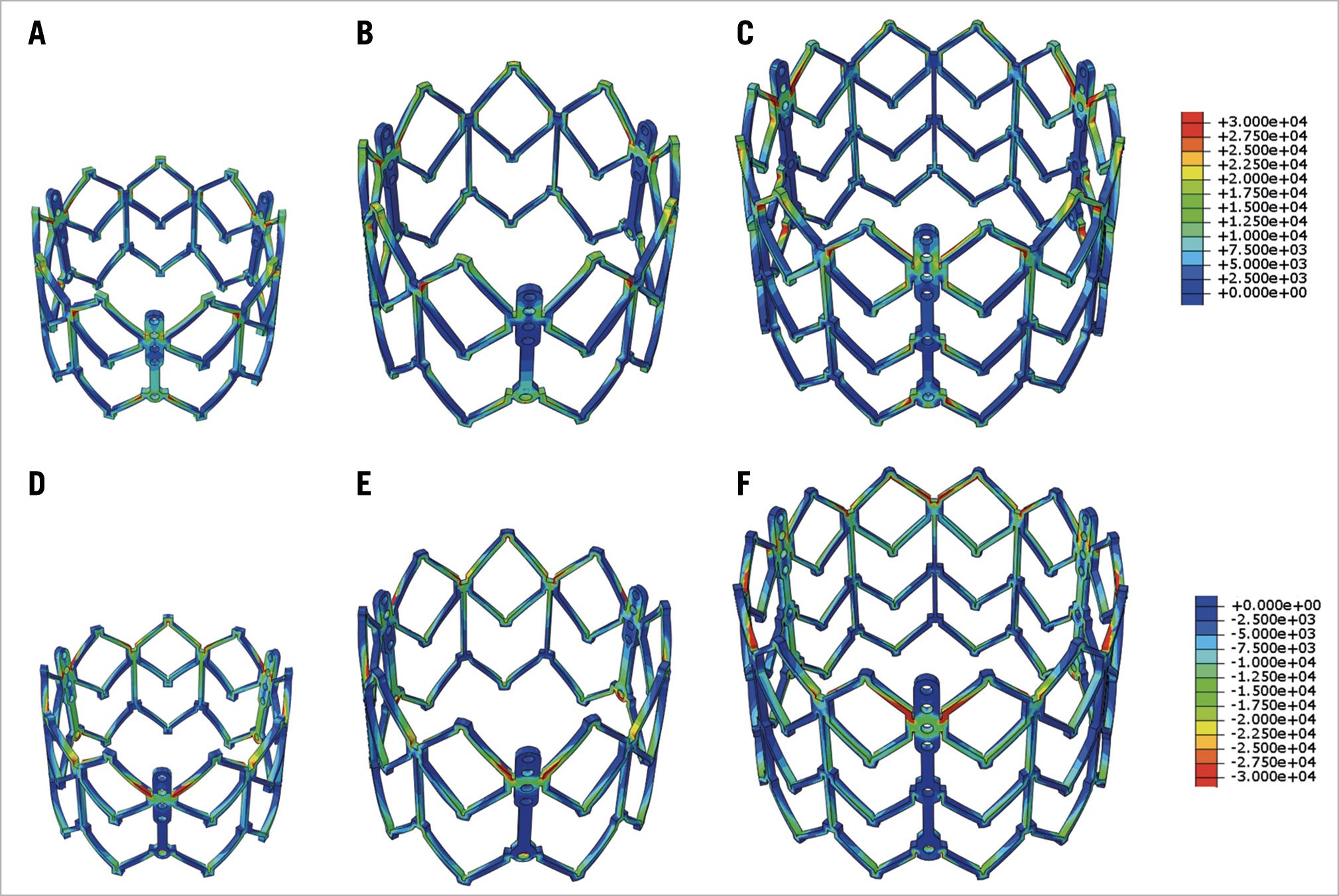
Figure 7. Maximum and minimum principal stress on transcatheter heart valve stent. Maximum (A6C) and minimum (dD6F) principal stresses of stent of 23 mm, 26 mm, and 29 mm SAPIEN XT at mean arterial pressure.
Discussion
Edwards balloon-expandable THVs, approved by the US Food and Drug Administration in late 2011, have revealed no structural valve dysfunction with maintenance of low gradients and excellent valve area at five years4. While short-term durability appears adequate, long-term follow-up for durability of these valve designs is needed. Biomechanical studies using FEA can provide insight into mechanisms of valve degeneration by non-invasive approaches. Our current study investigated the impact of THV size from the same generation of balloon-expandable THVs on leaflet and stent stresses, which may impact bioprosthetic valve durability. Stresses on leaflets and stents of three different sizes of SAPIEN XT were computationally determined and compared. Our study established the benchmark to access the size effect on the long-term durability of bioprosthetic THVs, as indications for TAVR continue to expand to lower risk and younger patient populations.
PEAK STRESS AND SIZE
Three different sizes of second-generation SAPIEN XT valve were available for different annulus dimensions. Commonly, patient annulus areas can fall into the grey zone between two THV sizes. In this study, peak stresses on THV leaflets, irrespective of region, increased with increasing THV size when examining THVs expanded to nominal dimension. Overall, median stresses for the entire leaflet increased with increasing THV size at nominal, fully expanded deployment states (Figure 5). This is explained by the in-plane force being roughly equal to the product of pressure and cross-sectional area. Thus, a larger valve has greater total force on the leaflets because of its larger cross-sectional area for the same pressure loading. Our results suggest that THV size selection may potentially impact long-term durability.
OPTIMAL TAVR SIZING
Clinically, optimal TAVR sizing balances ideal haemodynamics with risks, such as conduction disorders and annular rupture. From a haemodynamics standpoint, larger TAVR size minimises transvalvular gradient and PVL, and maximises effective orifice area to decrease patient-prosthesis mismatch. PVL results from lack of congruence between annulus and THV, and is related to undersized THV prosthesis, device malpositioning, heavily calcified bulky native aortic valve cusps, and/or bicuspid valve23. Larger baseline annular coronal and oblique sagittal dimensions were found in patients with significant PVL24. Low cover index was also associated with PVL, suggesting that THV oversizing was necessary to reduce PVL25. From a patient-prosthesis standpoint, a larger THV size leads to less patient-prosthesis mismatch26, which affects mortality27. On the other hand, oversizing a THV can compress the conduction system, increase the rate of permanent pacemaker implantation, and increase risk of annular rupture when LVOT calcification is present25.
In this study, we examined the impact of oversizing a smaller THV vs undersizing a larger THV for annulus sizes within the grey zone, and examined differences in leaflet stresses as a potential indicator for long-term durability. Undersizing the larger THV led to significantly lower leaflet stresses than oversizing the smaller THV, which may be another clinical consideration when choosing between two TAVR sizes. Overall, for annulus sizes that were clearly within the 23 mm, 26 mm, or 29 mm XT sizing guidelines, the larger THV had higher peak stresses which may lead to earlier THV bioprosthetic degeneration. In comparison, other computational studies examined how THV underexpansion affects leaflet stress, concluding that peak leaflet stress increased with more underexpansion12,28. For a given THV size, greater degrees of underexpansion were unfavorable compared to nominal deployment12,28. However, in these prior studies, only one THV size was tested with varying degrees of underexpansion, and did not account for an alternative THV size option for a given annulus size.
TAVR physicians must exercise their best judgment when choosing the optimal THV size within the grey zones based upon current practices, the finite number of THV sizes available, patient anatomy, including LVOT calcification, sinus effacement, and sinotubular junction dimensions, as well as optimal haemodynamics minimising PVL, to achieve ideal clinical outcomes. With multi-factorial risk factors for bioprosthetic valve degeneration, choosing the THV size based upon leaflet stresses to optimise long-term durability is yet one additional procedural consideration that could be factored into clinical decision-making to offer the benefit of longevity. Further clinical study will be needed to correlate calculated leaflet stress results with valve durability and loss of collagen integrity.
Limitations
The 23 mm, 26 mm, and 29 mm SAPIEN XT valves were chosen for controlled comparisons within one generation of balloon-expandable THV to investigate the impact of size on THV leaflet stresses. Given that the limited access to THVs for research purposes, complete sizes of SAPIEN 3 valves were not available to conduct this study. Given the SAPIEN 3 also has grey zones that accept either an oversized smaller THV or an undersized larger THV, these computational simulations examining leaflet stresses in a similar leaflet design across sizes are still translatable clinically. This study did not take into account leaflet damage from the crimping and ballooning process which occurs during TAVR. Studies have demonstrated that crimping physically damages THV leaflets and may weaken leaflets and increase leaflet stresses1. We did not destroy our THVs to test their leaflets for exact material properties given the rarity of obtaining THVs and the need for future TAVR experimental in vitro testing which were beyond the scope of this study. As such, we utilised excised leaflets from surgical bioprostheses to determine material properties for THV leaflets. While treatment processes for both Edwards valves are expected to be the same, thinner pericardial leaflets used in TAVR may have slightly different material properties6 than were represented here. As stent and leaflet stresses cannot be directly measured, there was no suitable method to perform experimental validation of stresses. Complex fluid-structure interaction simulations were not incorporated and were beyond the present scope of this study. Lastly, patient-specific simulations of each of the THV sizes were not performed, given that a single patient would only be able to provide a post-TAVR CT of one THV size and not yield suitable information regarding the second THV size when choosing between two sizes.
Conclusions
We studied the impact of balloon-expandable THV size on leaflet and stent stress in this study by comparing the same generation of THV with three available sizes. Larger THV sizes had greater leaflet stresses and may be more prone to earlier degeneration. On the other hand, when choosing between two THV sizes within the grey zones of annulus sizing, undersizing the larger TAVR resulted in lower leaflet stresses than oversizing the smaller THV. Sizing THVs currently takes into account annular measurements from CTA, as well as potential for PVL, patient-prosthesis mismatch, and risk of permanent pacemaker implantation and annular rupture. The results from this study shed light on another factor, leaflet stresses and THV size. Correlation with further clinical studies will be essential to correlate stresses with valve durability.
Impact on daily practiceFor some patients, the measured annulus size falls within the grey zone of THV sizing and is suitable for two THV sizes, depending on the degree of oversizing/undersizing. We performed finite element analyses of 23 mm, 26 mm, and 29 mm second-generation balloon-expandable THVs to determine the impact of device size on leaflet stresses, as a surrogate for durability. Larger THV sizes had higher peak leaflet stresses. However, for annulus sizes within the grey zone between two THV sizes, stresses were reduced when using an undersized larger THV than oversized smaller THV deployed in the same annulus size. The choice to size upwards in the grey zone may lead to improved long-term valve durability. |
Funding
The study was funded by the University of California Proof of Concept grant #246590, National Institutes of Health R01HL119857, and American Heart Association Postdoctoral Fellowship 16POST31420013.
Conflict of interest statement
E. Tseng and L.Ge are founders of ReValve Med, Inc. D. Dvir and J. Ye are consultants for Edwards Lifesciences. The other authors have no conflicts of interest to declare.
