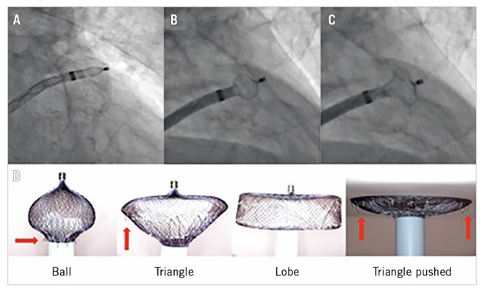
Figure 1. Evolutionary steps in safer deployment of the AMPLATZER Cardiac Plug and the AMPLATZER Amulet device. “Unsheathing” in
the left atrial appendage (A) to form a “ball” to enter (B) to create a “triangle” for harmless device pushing in shallow anatomies (C).
Gradual and controlled pushing of the delivery wire forms the Amulet lobe in different ways and shapes (D). The “ball” shape is used for
initial engagement and rotation/orientation of the sheath as the stabilising wires (red arrows) are close to the sheath and cannot damage the
LAA wall, whereas the “triangle” shape is used to push against the LAA wall as the distal lobe pin is retracted inside the lobe, but without
rotating the device as the stabilising wires are now exposed (red arrows).